Architectural CAD Drafting
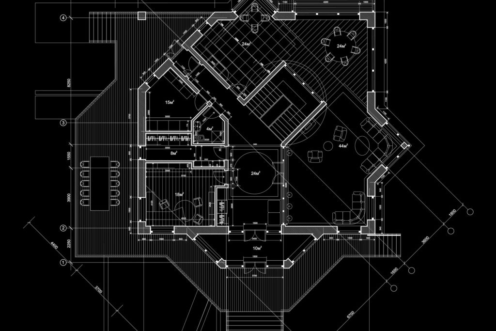
Key Aspects of Architectural CAD Drafting: Floor Plans: Detailed, scaled representations of the layout of rooms, walls, doors, windows, and other structural elements within a building. These drawings typically show dimensions, materials, and the overall arrangement of spaces. Elevations: Drawings that depict the exterior view of the building from different perspectives (front, side, or rear). Elevations help in understanding the height, scale, and materials of the building. Sections: Cross-sectional views that illustrate the interior components of a structure. Sections cut through the building to reveal the relationship between floors, walls, ceilings, and other vertical elements. Details and Callouts: Close-up drawings that provide detailed information on specific elements of the design, such as door/window frames, staircases, and materials used. Callouts are often used to point out specific parts of the design in a drawing. Site Plans: Depict the layout of the building in relation to its surrounding environment. They show the placement of the building on the site, landscaping, utilities, driveways, and topography. 3D Modeling: Many CAD programs now include the ability to create three-dimensional models of architectural designs. This allows for a more immersive visualization of the space and a better understanding of how the finished structure will look and function. Details on Materials and Finishes: CAD drafting often includes annotations about the materials, textures, and finishes to be used, which helps in construction and material procurement. Structural and MEP (Mechanical, Electrical, and Plumbing) Drawings: CAD can integrate structural engineering drawings and MEP designs to provide a holistic view of the entire building system, ensuring all parts fit together properly. Code Compliance: Architectural CAD drafts must adhere to local building codes and regulations. These standards are incorporated into the drafting process to ensure that the design is safe and legal.
Read More